Fixing the Tailstock

The Realbull tailstock is, in comparison to the Sieg model, massive. It weighs about 10 lbs and sits on a 1/2″ thick cast iron base and comes with a substantial cam-lock.  All as part of the design.

The flaw in this design is the lack of adjustments to align the tailstock to the headstock spindle. In short aligning this tailstock has been an exercise in frustration.

This frustration caused serious inspection of the tailstock which revealed some issues that should have prevented this lathe from leaving the factory but, of course, didn’t.  This article discusses these issues in depth and shows how the shortcomings were fixed to produce an excellently operating tailstock.

Tailstock castings and adjustment screws

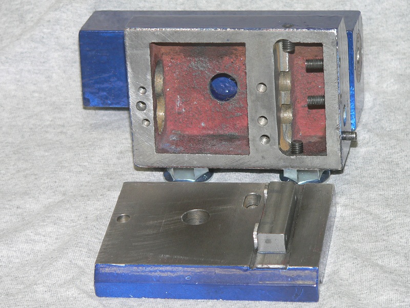
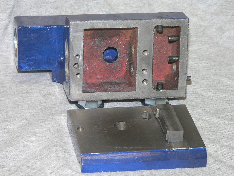
Although the picture above does not show it clearly, block “2” is about 1/2″ taller than the rest of the base.  The picture also shows four adjustment screws “1”.  The two on the right (angle screws) are intended to push the block “2” against the inner bulkhead of the upper casting or body and the front/back screws (traverse screws) set the body’s front/back depth.  Once aligned the socket head cap screw “3” secures the base to the tailstock body in the threaded hole “4”.

A traverse or offset of the tailstock is accomplished by loosening the two angle screws and adjusting the traverse screws by equal amounts and retightening the angle screws.

Given this arrangement, it should be fairly easy to align the tailstock to the headstock, but there are several issues that are not yet resolved.

  1. There is no provision for vertical alignment of the tailstock. This is not impossible to overcome with shims and their use is probably a better solution.
  2. The block on the base is not “finished” in any meaningful sense of the word.
    Because the block isn’t finished moving the  body throws out all other adjustments. If the block were ground square (and perpendicular to the “V” on the bottom) such adjustments and movements would be possible with predictable results.
  3. The slot for the lockscrew is inaccessible when the tailstock is mounted.  Notice in the picture of the base above the slot for the lockscrew.  Inexplicably, this lockscrew cannot be accessed while the tailstock is mounted on the lathe as that portion of the tailstock rides on the rear bedway. So once the tailstock is aligned, you would have to hang the tailstock at least halfway off the back of the bed to lock it down risking the adjustment.
  4. For the body to move relative to the base without disturbing the tailstock’s height the top of the base must be in a parallel plane to the rear flat of the bed.

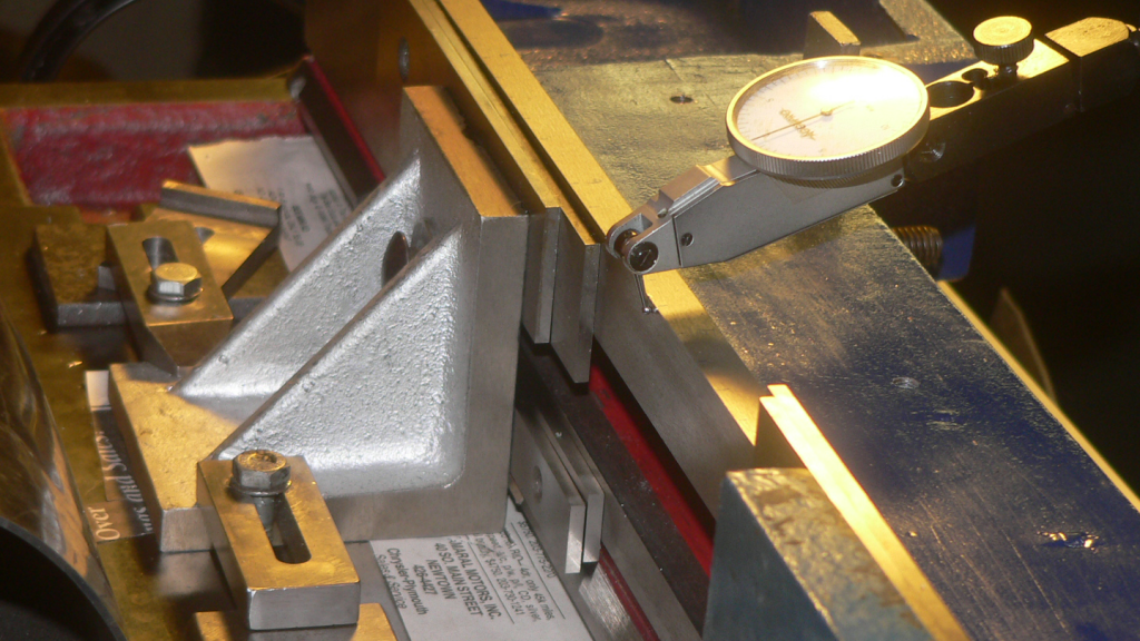
Realizing the last requirement I set out to measure how flat the base was.

Setup to measure tailstock base flatness relative to the lathe bed

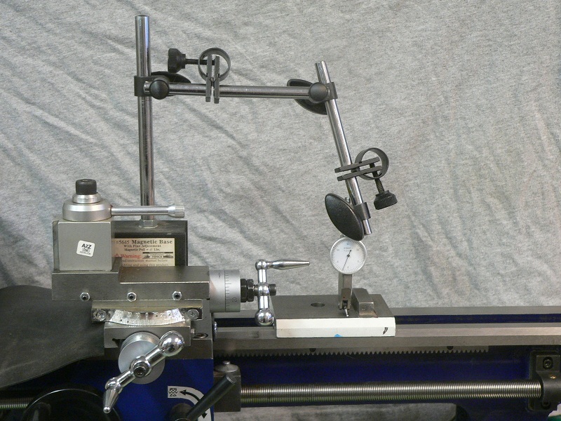
The setup was simple since the flatness relative to the bed is the important criteria.  A DTI was placed on the carriage and touched to each of the tailstock bases’ four corners.

Results of measurements showing eighteen thousands across opposite corners of the tailstock base

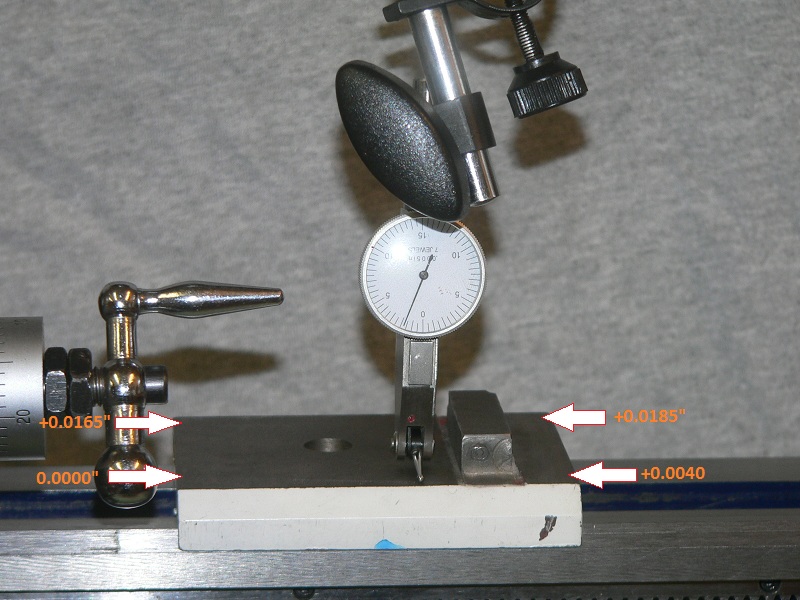
As you can see flatness is not great! There is a total of 18 thousandths from the front left corner to the back right corner. There seems to be a rise of 2-4 thousandths along the X-axis as you move away from the headstock and there is 14-16 thousandths rise along the Y-axis front to back.

I’d like to measure the bottom of the body as well, but can’t figure out what to use as a reference. Please make any suggestions in the comments.

Assuming that the tailstock body is fit to the base in it’s “normal” position it is entirely possible to align the tailstock for the normal position.  The non-planar nature of the top of the base is a problem if one actually wants to use the offset feature of the tailstock as this design appears to allow.

In this case there is a run of about 8 thousandths per inch across the base, and the traverse screws are about 1/2″ long, there will be a vertical change of 4-5 thousandths in using the offset feature of the tailstock.

From the normal or centered position, the tailstock will gain or lose 0.002″ vertically.  While this is acceptable for some applications this shows another instance of this lathe not really being ready for use as it left the factory.

The ideal resolution would have been to regrind the surface flat, grind the baseblock to a correct angle relative to the “V” on the base and regrind the tailstock body.  Unfortunately I did not have access to a surface grinder so such an extensive fix was not realistic.

It is notable that regrinding as a fix would probably leave the tailstock well short of meeting the vertical height of the spindle.  Assuming that 12-15 thousands would have to be removed from the base AND the body it’s not hard to imagine the tailstock being vertically under the spindle axis by 0.030″.  This could be shimmed but the shims would interfere with any offset operation making the entire effort of fixing the tailstock pointless.

In the end, I decided to leave the base and body alone and that one aligned the tailstock would never be offset.

In summary the base is not flat, the base block that dictates the angle is not smooth and it’s difficult to determine what surfaces are mating, and it’s difficult to lock in a setting since the lockscrew is inaccessible when the tailstock is mounted on the lathe.

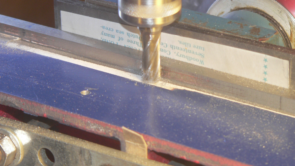
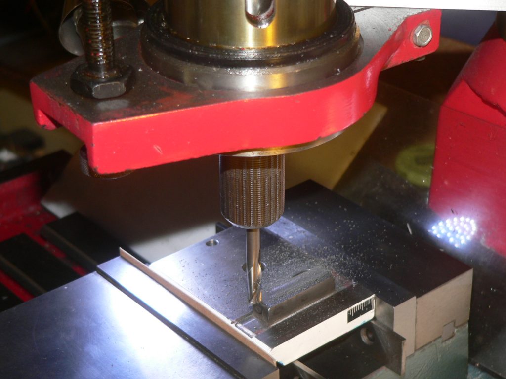
With these issues in mind planning was started for a milling session on the base with the following objectives

  1. Create a lock nut in the front of the tailstock:  There’s plenty of room on the front bulkhead for another lockscrew, right in the middle where you can reach it from underneath the bed.
  2. Recess the front center of the block so that it makes contact at the outside edges:  This would reduce the contact area making the angle easier to control. The recess is minimal, about ten thousandths or so.
  3. Reduce the height of the block:  While there was likely sufficient room the top of the block was uncomfortably close to the cam lock driver. Since the base was already being milled, it was easy to remove about 0.012″ and ensure nothing was going to rub.
Setup for base milling operation
Base milling operation objectives
Bottom of base after milling

With these modifications made, it became very simple to bring the entire tailstock within 0.004″ in any plane or rotation of interest. When trying to make it better than that, things became unreliable again.

Note: The blue tailstock is not a replacement but the original tailstock. While I had the tailstock all cleaned from the milling operation there was a several days reprieve from the cold here in New England so the opportunity was taken to paint it to match the bed. Turns out white is a terrible color for a machine tool.

At this point attention was turned to the tailstock body.  In particular the contact area of the inner bulkhead.  When the base block had been recessed to set the contact surfaces the body’s bulkhead area was smoothed by file.  When problems persisted in alignment the body was inspected again and it was realized that the bulkhead contact wall is not perpendicular or at an acute angle to the base block. As a result; when the angle screws are tightened the tailstock body raises AWAY from the base. If the wall were at an acute angle the force would be downward reinforcing the angle screws tension.

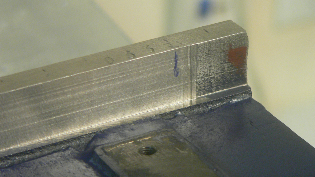
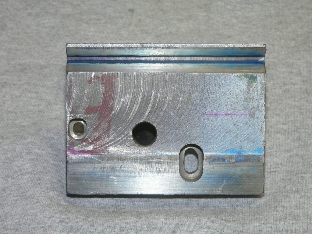
So after identifying this issue with the body the tailstock body and base were taken back to the mill.  The bulkhead was measured as being about 5 degrees off perpendicular to the base. The tailstock body was milled to make the bulkhead perpendicular to the bottom and the base block was again milled to resquare the block on both the bulkhead mating surface, with a 0.025″ relief in the center. I also ensured that the ends of the block were squared to mate with the traverse screws in the body. This next picture shows the results.

Base and body after making inner wall perpendicular to base.

Why was the bulkhead at a 5 degree angle? I can honestly say I do not know. My best guess is that it was an error at the factory. I’d be very interested if anyone else with this style of tailstock could look at this feature and let me know the angle of their bulkhead.

By the time that was done about 0.040″ had been removed between the block and the bulkhead. This meant that the tailstock body would sit further back on the base. Since the base is NOT planar (refer to discussion earlier) I did not want the body shifting this much so I was going to need some fairly thick shims. I also wanted to be able to control the angle so I tapped 3×0.5 mm into the base block and made thick shims with a countersunk 3mm screw. The 3mm size was the smallest countersunk screw I could find on a Sunday afternoon at the local hobby shop. This next picture shows the base block shims fairly well.

Base and body with thick shims

So this story is finally winding down to the end. With all these modifications, I was easily able to get the alignment within 1.5 thousandths. I still noticed a tendency for the body to rise away from the base when using the traverse screws, but the angle screws now worked just as expected.

I have not looked carefully at them, but I suspect that the traverse screws are not tapped perpendicular to the body so there is some upward force. It was not nearly as bad as the angle screws before fixing the bulkhead and was easily compensated for.  Should the base have to be returned to the mill at some future date it would make sense to consider milling the end faces of the base block to an obtuse angle to the base.  This would have the effect of forcing the body down as previously discussed.

For a tailstock on this class of lathe 1.5 thousands is not bad but I wanted to see how far I could dial it in.

The final issue came when tightening down the lock screws on the bottom of the base.  It was very easy to throw the alignment out by 4-5 thousandths during tightening. Fortunately, this turned out to be very repeatable and predictable so I took careful note of the direction of misalignment and compensated to the other side. By using this method and carefully adjusting the torque on the lock screws, I was, in the end able to get the tailstock with 0.0005″ (yes that’s a half thousandth) with the tailstock ram retracted and extended. Alignment beyond that is beyond both my ability to measure and my patience.

The general design of this tailstock is better than the traditional Sieg design. The increased mass of the tailstock, the hefty camlock mechanism with nice features such as a detent in the lock position, handle tension adjustment, and oil ports make me look favorably upon the tailstock itself.

Perhaps I simply received a bum unit but the non-planar nature of the base, the bulkhead being off angle, no ability to lock down the front of the tailstock and the difficulty I had in being able to adjust it out of the factory would be enough to give most people fits.  It is an unfortunate testament to the lack of quality control and certainly not a fitting execution of an otherwise admirable design.

If I received another of these units, I would immediately check the flatness of the base and the bulkhead angle again. I suspect that while the bulkhead may have been an error, my feel is that the base is never flat or parallel to the ways. Again, I would be very interested to know the results should anyone ever measure this. Had the bulkhead angle been correct to start, I probably would have been able to adjust the tailstock to an acceptable level without modification at all.

Even if the tailstock came perfect I would also immediately add the front lockdown screw slot. It seems a simple thing, but in the final adjustments this was very helpful.  When the lockdown was tight, the angle tended to be adjusted more than a traversing move and visa-versa. This was the motion that let me dial in the final adjustments as finely as I did.

Let’s Talk About the Mini-lathe Saddle

The saddle (or carriage) of the mini-lathe travels the length of the bed for turning operations and provides the base for the cross-slide to travel perpendicular to the spindle axis for facing operations.  Since the saddle on the mini-lathe is a single piece with no readily reversible method of field adjustment; the saddle is fitted to the bed in the factory.

It had been determined by blueing that the inside V of the saddle makes contact at four points on the bed’s front inverted V.  The rear contact surface is a flat area with no features that assist in preventing the saddle from twisting.  It is the four points on the front that prevent twisting and set the angle relative to the bed that forces cross-slide travel to be perpendicular.  If an adjustment in the angle is required; removal of material from opposite points on the saddle’s internal V will adjust the angle of the cross-slide while still keeping the saddle stable on the bed.

The cross-slide itself mounts on dovetails ground in the saddle.  Provided the dovetails are straight and parallel the cross-slide plate will travel firmly and tightly provided the cross-slide gib strip fits well.

The last critical piece of the saddle is the surface that the bed gibs are bolted to.  It is simplest if this face is parallel to the bed’s underside as that simplifies the shims required.  However this surface cannot be proud of underside of the bed.  If this surface extends beyond the bed there is no way to tighten the bed gibs sufficiently for the bed gibs to make contact with the under side of the bed.  The result would be to have the saddle lift in operation.

It was initially appeared difficult to measure any of these relationships to determine if changes needed to be made since there is no obvious repeatable reference.  Where did one start?

After long consideration and discussion it seemed the best choice was to assume that the flat portion of the cross-slide dovetail was flat and both sides of the dovetail were ground to the same plane.  This simplifying assumption provided for a quick check on the V of the saddle, the flat portion that mated the rear of the bed, and the surface where the bed gibs mounted.

Consider that if the saddle in turned upside down and the dovetail flats placed on parallels such that the tops of the parallels are level then the following should also be true if the saddle is fit correctly

  •  A 3/8″ to 1/2″ (10-12 mm) drill rod placed  in the V will be level
  • The flat area that mates to the rear of the bed will be level
  • The mounting surfaces of the bed gibs will be level

In other words, the horizontal flats of the cross-slide dovetail, the four points of contact in the V, the flat on the rear of the saddle and both bed gib mounting surfaces are all in parallel planes and that this can be demonstrated in a single measurement setup.

Using the cross-slide dovetails as the reference also provides simple and secure mounting of the saddle  on a mill for any work required.

Returning to the immediate issue of the realbull mini-lathe; having finished milling the lathe bed and lapping the underside bed surfaces the gibs were bolted to the saddle (without any shims) and mounted on the bed.  The gibs stuck and jammed into the underside of the bed.  Shimming was attempted but the thickness of the shims varied widely (around 0.006″) from one end of the gib to the the other.  The gibs had already been lapped and known to be straight.  This revealed that the surface the gibs mounted against on the saddle were out of parallel.

It was entirely possible to get the correct set of shims to make the gibs parallel but it was not the correct solution.  To fix this meant going back to the shop to mill those surfaces.

Setup for milling the mini-lathe saddle

And so it was done.  The photo shows the parallels being used to raise the dovetails and base the cuts on the horizontal portions of the cross-slide dovetails.

Fortunately for this mini-lathe, no further work was required on the saddle.  After this milling operation the gibs mounted with shims around .014″ and the saddle traveled the entire length of the bed with no rocking, twisting or lifting in operation.

The perpendicular travel of the cross-slide was determined by mounting a indicator on the cross-slide and ensuring the forward most and rear most points of the spindle face are equal.  Any deviation indicates the cross-slide is out of square as the the spindle had been previously fitted and made parallel to the bed.

The squareness of the cross-slide was double checked by mounting a chuck on the spindle and chucking a bent rod.  The end of the rod was placed to inscribe a circle around six inches diameter.  The DTI was used to measure the fore most and rear most points of the inscribed circle to ensure there was no difference in the measurements.

While no measurable deflection was seen measuring the spindle face, there was just over a thousandth of an inch measured on the six inch inscribed circle.  I think it’s likely that I did not get the exact same point on the end of the rod between front and back and it may be that if the end of the rod were rounded to a true semi-sphere I would get a different, more accurate measurement.  I decided to live with 0.001″ and move on.

Fixing the Lathe Bed

Getting to the Problem:

It all starts with the lathe’s bed. The Realbull 7×14 mini-lathe had been purchased and delivered. It was time to start the normal routine of getting it to work smoothly.

A primary requirement of satisfactory lathe usage and results is to have a saddle that slides smoothly without binding over the entire length of the bed but does not rock at any point. On a stock mini-lathe there is a gib strip that is held to the saddle by three socket head cap screws. The strip is set to the width of the bed by two set screws that push the gib strip away from the saddle. The set screw design of the mini-lathe is problematic as it produces point contacts between the saddle bed instead of contact surfaces making it much harder to get a good fit. Further complicating the problem is that the gibs themselves are fairly thin and it is easy to warp or crack the gibs with these opposing forces.

There are many modification designs available to fix this particular design flaw of the mini-lathe but the simplest answer to the problem is lapping and shimming the gibs to fit so they can be torqued down to the saddle providing surface contact between the gibs and the underside of the bed.

This approach is very simple but it may wear after a few years of heavy use. In that case it will be necessary to adjust the shims to be thinner.

Lapping the gibs is tedious but straight forward work. By running the gibs through a series of increasingly fine silicon carbide paper any minor fluctuations are worked out of the gib and the machinist ends with a flat surface to match the underside of the bed. After a few hours of lapping it was time to fix the shims and finish the saddle.

That is the theory and as is often the case theory was left behind and the real world intervened.  After several hours of frustrating work attempting to fit the gib strips it was evident that something was seriously wrong.

The gibs had been lapped till they were flat on the surface plate and a caliper showed no deviation in thickness.  The shims being used was standard brass shim stock from .008″ to about .020″.  Regardless there was no shim thickness that didn’t either bind up the saddle somewhere along the way or became so loose on the bed that I could see daylight between the saddle and the bed. It was at this point that serious inspection of the lathe bed began.

If you consider the bed/saddle section below it’s clear that in order for the saddle to ride smoothly along the length of the bed several things must be in close alignment.

End section of lathe bed showing relationship to saddle and gib surfaces.
End section of lathe bed showing relationship to saddle and gib surfaces. (Note: shim shown in gray)
  1. The front and rear outside thickness of the bed must be uniform along the length of the bed (bed shown in blue)
  2. The top and bottom of the rear bed (outside) must be in parallel planes as well as the underside of the front outside bed.
  3. The inverted “V” of the saddle (in red) must make good contact with the inverted “V” of the bed to prevent twisting of the saddle on the bed.
  4. The bearing surface of the saddle must make good contact with the top of the bed to prevent tipping or rocking of the saddle.
  5. The gib mounting face (in purple) of the saddle must be in a plane that is parallel to the saddle rear bearing surface and parallel to the plane of the bottom outside edges (front and rear)
  6. The gibs top and bottom surfaces must be in parallel planes.

Of course, these points are listed here as though this was immediately known and perfectly understood. I assure you that was not the case.  At that time the geometry of the bed and saddle hadn’t yet been seriously considered. You’ll see however as the story progresses that most of these items had some kind of problem that needed to be resolved.

Measuring the Problem:

What was plain at that time was that the bed needed to be checked. As with any type of measurement you need a reference but there is no obvious point of reference and the shop had no surface plate large enough to handle the lathe bed.

After some consultation it was decided that to assume and trust that the top surface of the bed was true.  Without access to a surface grinder or a large surface plate there was simply no practical way to verify this assumption.  However, this surface is ground at the factory and just had to be trusted.  For those readers who are familiar with the 7×12 Yahoo Group this belief that the top surface of the bed is ground true will be familiar.

So starting with that assumption the thickness of the bed was measured. The procedure is very simple. Using a fine black sharpie marker mark off 1/2″ increments along the bed. After ensuring there is no paint on the underside of the bed use a micrometer to measure the bed thickness every half inch along the length of the bed. The rear bed which is flat both top and bottom is obvious. For the front bed thickness measure from the top of the inverted “V”.

The results of this simple procedure was shocking! The front thickness of the bed had a difference of 15 thousandths (0.015″) with the headstock end of the bed being thinner. There was also a difference of 17 thousands (0.017″) on the read bed running in the other direction (tailstock end being thicker). It was no longer any surprise that the saddle could not be fit correctly.

But what to do?? Again consulting a friend we discussed the situation and I agreed to bring the whole lathe down to his shop. After confirming the measurements in his shop it was obvious that some machining was going to have to be done to the bed to bring it close enough to lapp the bed into final fit.

Fixing the Problem:

Machining the bed may seem a bit drastic, but 17 thousandths is a lot of material to remove. Filing would have been very difficult and the chances that the bottom would have been parallel to the top (see point two above) seemed remote. In the end, there was nothing to do for it but mount the bed onto the mill and make some very careful measurements to make sure that the cuts were made right the first time.

It would have been nice to be able to mount the bed upside down on the table and use a fly cutter to sneak around the feet of the bed. That would have made for a single setup and put the bottom of the front and rear in the same plane. That wasn’t done because there was concern that the interrupted nature of the cut would possibly make the fly cutter work loose during the machining or that the finish would be unsatisfactory for the lapping on the underside of the bed that needed to follow.

More importantly however was that the Y axis of this particular mill wouldn’t have allowed fly cutter to clear the bed. This meant that the bed top had to be mounted parallel to the Z axis and a regular end mill would be run down the length. This would require two setups.

Lathe bed vertically clamped to mill table

The above picture shows the setup pretty well. The bed was bolted to a pair of angle plates using parallels to clear the V of the front bed. This assembly was then mounted onto the mill and put in place using a DTI indicated along the top and the rear face of the bed. Indicating along the rear face of the bed was important to ensure that the end mill did not dig into the body of the bed needlessly.

End mill taking a cut on the bed rear bottom

As you can see the depth of rear underside of the bed was not consistent along the length of the bed. This is not a critical measurement and the end mill was allowed to remove material as needed. After the rear of the bed was complete the bed was flipped end for end, set up in the same manner and the front side of the bed was machined.

While the depth of the cut is not critical for the rear, it is more important on the front side. The rack for the saddle pinion mounts onto the face perpendicular to the lathe bed immediately under the bed. To ensure that there was no lip to hang up the rack during assembly a small amount of material was intentionally taken from the rack mounting face in the same operation that cut the underside fo the bed.

One additional challenge of this setup was that the bed of the 7×14 was just beyond the capacity of the mill. As a result we ran a little short on the front side pass

The end of the bed was later filed down to be narrower than the rest of the bed. This was perfectly acceptable as this portion of the bed is outside the pillow blocks holding the lead screw and the gibs cannot reach this section in operation.

End of front side of bed showing serial number 33

You can now see several of the points I’ve been making in this picture. It is plain where a few thousands of the front face of the bed base have been removed to ensure the rack would remount easily. On the front face of the bed you can also see the remains of the initial 1/2″ increments used to make the measurements. You can also see my serial number. If this lathe is actually the 33rd one off the line it would explain many of the problems with this lathe.

And We’re Done (not quite!):

With the thickness of the bed now within a thousandth or two the pieces of the lathe were packed up and bought back to my shop with the intention of getting a fine finish on the underside of the bed by lapping to match the gibs. That is when it became apparent that several of the other important planes were not parallel to the bed either.

I’ll discuss that further in our next installment.

Realbull 7×14 Mini-lathe

This is the shops Realbull 7×14 mini-lathe, Serial Number 033. At the time it was purchased (spring 2008) Realbull lathes in the United States were not nearly as common as the Sieg models. I had read about some of the design differences and thought the Realbull would be a nicer unit but since it wasn’t imported into the U.S. I was ready to purchase a Sieg unit from one of the many vendors who import mini-lathes. About that time a U.S. distributor appeared that was importing the Realbull models so one could actually be purchased. The unit was purchased and received in May of 2008.

Front view of Realbull 7x14 mini-lathe
Front view of Realbull 7×14 mini-lathe

In comparison to most of the other stories I’ve heard about sloppy workmanship and quality control on the Chinese mini-lathes, both Realbull and Sieg, this particular unit has been a true nightmare. It took the better part of ten months, many hours, and an extra large dose of help from a friend who has a mill to get this lathe into service.

In truth the lathe never should have left the factory. In truth, I probably should have returned it. In my defense all I can say is that I expected some fixup, as that is common in this class of machine, however the extent of the next problem never really became clear until the previous problem had been solved. I had no idea, until I was at the end, how much work I was setting myself up for. As far as the factory quality is concerned, I can’t come up with any excuses!

You will find on this site posts detailing the many steps that had to be taken to make this unit perform as it should. At the start, I had very little experience using lathes but by the end I have come to understand how a lathe works very well. Perhaps I should be thankful that I had such a dog of a lathe at the start.

Having to machine just about every major part of this lathe helped me greatly to understand how the lathe comes together and just what it takes to get a good fit on the moving parts. As a result I find I don’t have any nervousness about making any changes to the lathe that come to mind. After all, it’s already better than it once was!

It is my hope that other hobby machinists will find these articles interesting academic reading and that they will never have to make any practical use of this. I should admit though I very often find my hopes dashed . . .


Next post in series: Fixing the Lathe Bed