

Getting to the Problem:
It all starts with the lathe’s bed. The Realbull 7×14 mini-lathe had been purchased and delivered. It was time to start the normal routine of getting it to work smoothly.
A primary requirement of satisfactory lathe usage and results is to have a saddle that slides smoothly without binding over the entire length of the bed but does not rock at any point. On a stock mini-lathe there is a gib strip that is held to the saddle by three socket head cap screws. The strip is set to the width of the bed by two set screws that push the gib strip away from the saddle. The set screw design of the mini-lathe is problematic as it produces point contacts between the saddle bed instead of contact surfaces making it much harder to get a good fit. Further complicating the problem is that the gibs themselves are fairly thin and it is easy to warp or crack the gibs with these opposing forces.
There are many modification designs available to fix this particular design flaw of the mini-lathe but the simplest answer to the problem is lapping and shimming the gibs to fit so they can be torqued down to the saddle providing surface contact between the gibs and the underside of the bed.
This approach is very simple but it may wear after a few years of heavy use. In that case it will be necessary to adjust the shims to be thinner.
Lapping the gibs is tedious but straight forward work. By running the gibs through a series of increasingly fine silicon carbide paper any minor fluctuations are worked out of the gib and the machinist ends with a flat surface to match the underside of the bed. After a few hours of lapping it was time to fix the shims and finish the saddle.
That is the theory and as is often the case theory was left behind and the real world intervened. After several hours of frustrating work attempting to fit the gib strips it was evident that something was seriously wrong.
The gibs had been lapped till they were flat on the surface plate and a caliper showed no deviation in thickness. The shims being used was standard brass shim stock from .008″ to about .020″. Regardless there was no shim thickness that didn’t either bind up the saddle somewhere along the way or became so loose on the bed that I could see daylight between the saddle and the bed. It was at this point that serious inspection of the lathe bed began.
If you consider the bed/saddle section below it’s clear that in order for the saddle to ride smoothly along the length of the bed several things must be in close alignment.

- The front and rear outside thickness of the bed must be uniform along the length of the bed (bed shown in blue)
- The top and bottom of the rear bed (outside) must be in parallel planes as well as the underside of the front outside bed.
- The inverted “V” of the saddle (in red) must make good contact with the inverted “V” of the bed to prevent twisting of the saddle on the bed.
- The bearing surface of the saddle must make good contact with the top of the bed to prevent tipping or rocking of the saddle.
- The gib mounting face (in purple) of the saddle must be in a plane that is parallel to the saddle rear bearing surface and parallel to the plane of the bottom outside edges (front and rear)
- The gibs top and bottom surfaces must be in parallel planes.
Of course, these points are listed here as though this was immediately known and perfectly understood. I assure you that was not the case. At that time the geometry of the bed and saddle hadn’t yet been seriously considered. You’ll see however as the story progresses that most of these items had some kind of problem that needed to be resolved.
Measuring the Problem:
What was plain at that time was that the bed needed to be checked. As with any type of measurement you need a reference but there is no obvious point of reference and the shop had no surface plate large enough to handle the lathe bed.
After some consultation it was decided that to assume and trust that the top surface of the bed was true. Without access to a surface grinder or a large surface plate there was simply no practical way to verify this assumption. However, this surface is ground at the factory and just had to be trusted. For those readers who are familiar with the 7×12 Yahoo Group this belief that the top surface of the bed is ground true will be familiar.
So starting with that assumption the thickness of the bed was measured. The procedure is very simple. Using a fine black sharpie marker mark off 1/2″ increments along the bed. After ensuring there is no paint on the underside of the bed use a micrometer to measure the bed thickness every half inch along the length of the bed. The rear bed which is flat both top and bottom is obvious. For the front bed thickness measure from the top of the inverted “V”.
The results of this simple procedure was shocking! The front thickness of the bed had a difference of 15 thousandths (0.015″) with the headstock end of the bed being thinner. There was also a difference of 17 thousands (0.017″) on the read bed running in the other direction (tailstock end being thicker). It was no longer any surprise that the saddle could not be fit correctly.
But what to do?? Again consulting a friend we discussed the situation and I agreed to bring the whole lathe down to his shop. After confirming the measurements in his shop it was obvious that some machining was going to have to be done to the bed to bring it close enough to lapp the bed into final fit.
Fixing the Problem:
Machining the bed may seem a bit drastic, but 17 thousandths is a lot of material to remove. Filing would have been very difficult and the chances that the bottom would have been parallel to the top (see point two above) seemed remote. In the end, there was nothing to do for it but mount the bed onto the mill and make some very careful measurements to make sure that the cuts were made right the first time.
It would have been nice to be able to mount the bed upside down on the table and use a fly cutter to sneak around the feet of the bed. That would have made for a single setup and put the bottom of the front and rear in the same plane. That wasn’t done because there was concern that the interrupted nature of the cut would possibly make the fly cutter work loose during the machining or that the finish would be unsatisfactory for the lapping on the underside of the bed that needed to follow.
More importantly however was that the Y axis of this particular mill wouldn’t have allowed fly cutter to clear the bed. This meant that the bed top had to be mounted parallel to the Z axis and a regular end mill would be run down the length. This would require two setups.
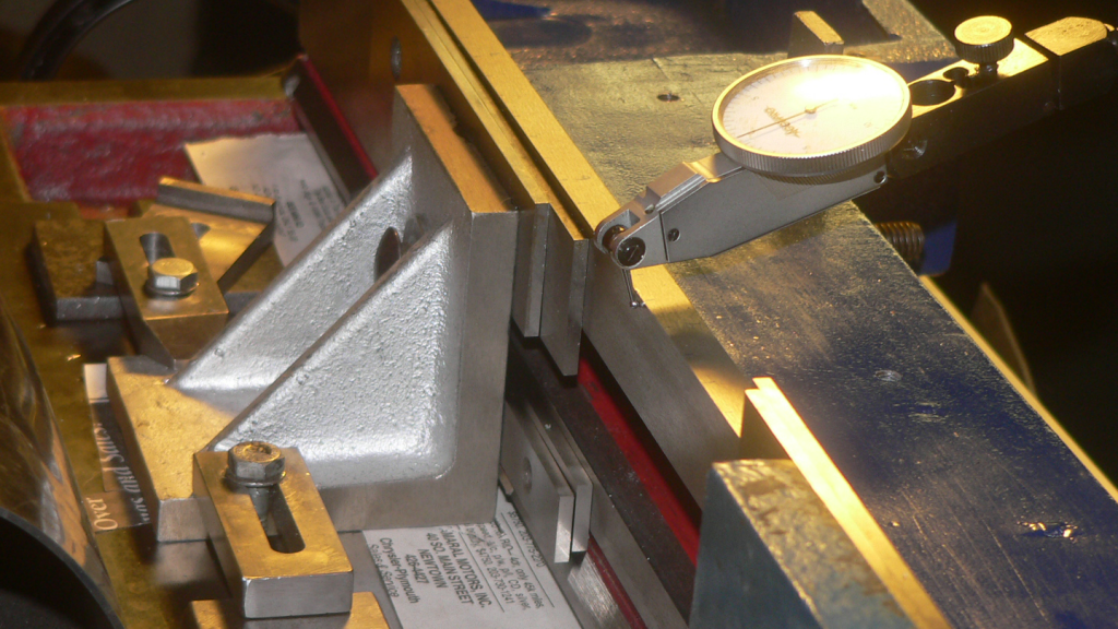
The above picture shows the setup pretty well. The bed was bolted to a pair of angle plates using parallels to clear the V of the front bed. This assembly was then mounted onto the mill and put in place using a DTI indicated along the top and the rear face of the bed. Indicating along the rear face of the bed was important to ensure that the end mill did not dig into the body of the bed needlessly.
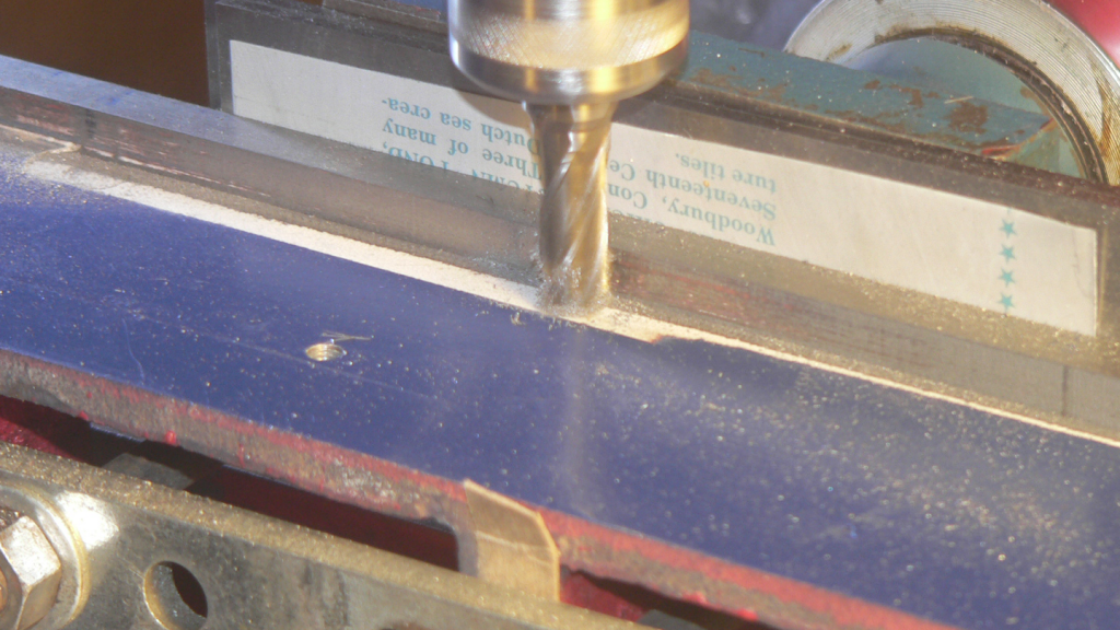
As you can see the depth of rear underside of the bed was not consistent along the length of the bed. This is not a critical measurement and the end mill was allowed to remove material as needed. After the rear of the bed was complete the bed was flipped end for end, set up in the same manner and the front side of the bed was machined.
While the depth of the cut is not critical for the rear, it is more important on the front side. The rack for the saddle pinion mounts onto the face perpendicular to the lathe bed immediately under the bed. To ensure that there was no lip to hang up the rack during assembly a small amount of material was intentionally taken from the rack mounting face in the same operation that cut the underside fo the bed.
One additional challenge of this setup was that the bed of the 7×14 was just beyond the capacity of the mill. As a result we ran a little short on the front side pass
The end of the bed was later filed down to be narrower than the rest of the bed. This was perfectly acceptable as this portion of the bed is outside the pillow blocks holding the lead screw and the gibs cannot reach this section in operation.
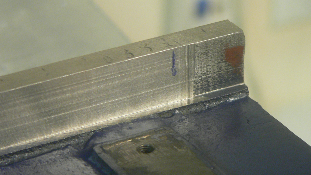
You can now see several of the points I’ve been making in this picture. It is plain where a few thousands of the front face of the bed base have been removed to ensure the rack would remount easily. On the front face of the bed you can also see the remains of the initial 1/2″ increments used to make the measurements. You can also see my serial number. If this lathe is actually the 33rd one off the line it would explain many of the problems with this lathe.
And We’re Done (not quite!):
With the thickness of the bed now within a thousandth or two the pieces of the lathe were packed up and bought back to my shop with the intention of getting a fine finish on the underside of the bed by lapping to match the gibs. That is when it became apparent that several of the other important planes were not parallel to the bed either.
I’ll discuss that further in our next installment.
